
Description
Product Description

KEY FEATURES
- Remote control via Modbus TCP/IP (customer’s PLC Master/BMS);
- Nominal airflow rate: 6,200 m3/h (up to 7,130 m3/h max);
- EC centrifugal fan, variable speed 25-100%;
- Water/air cooling coil with PID temperature control;
- G4/Coarse 60% pre-filtration + ePM1 55% (F7) absolute filtration;
- Fully removable front inspection doors for front-access maintenance;
Product Description
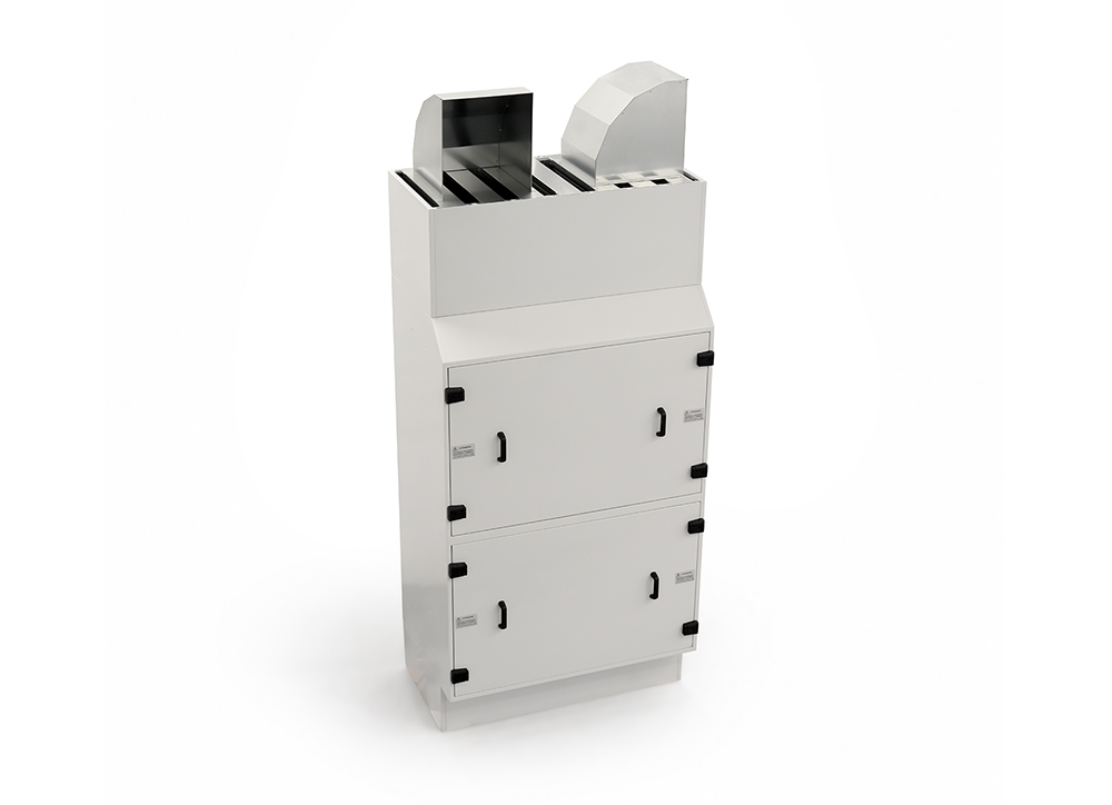
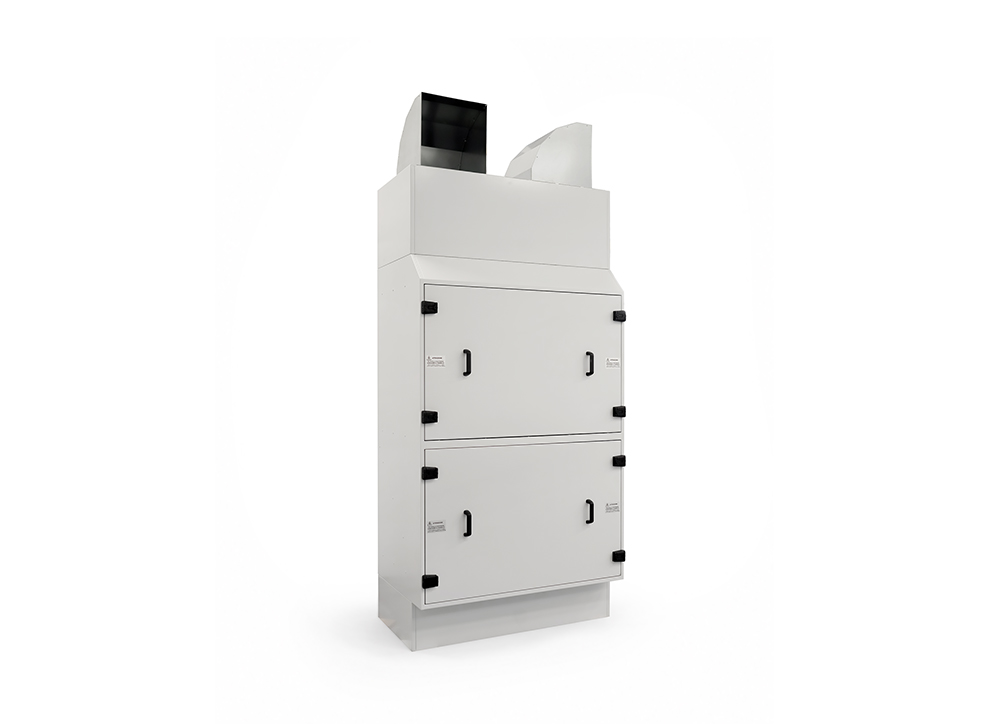
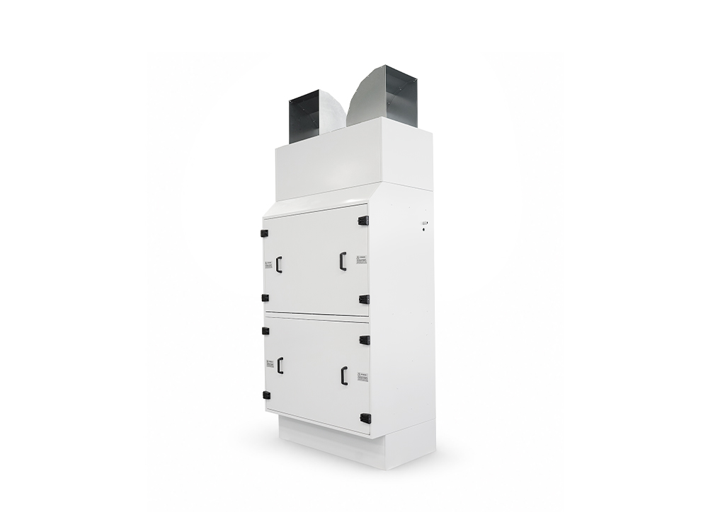
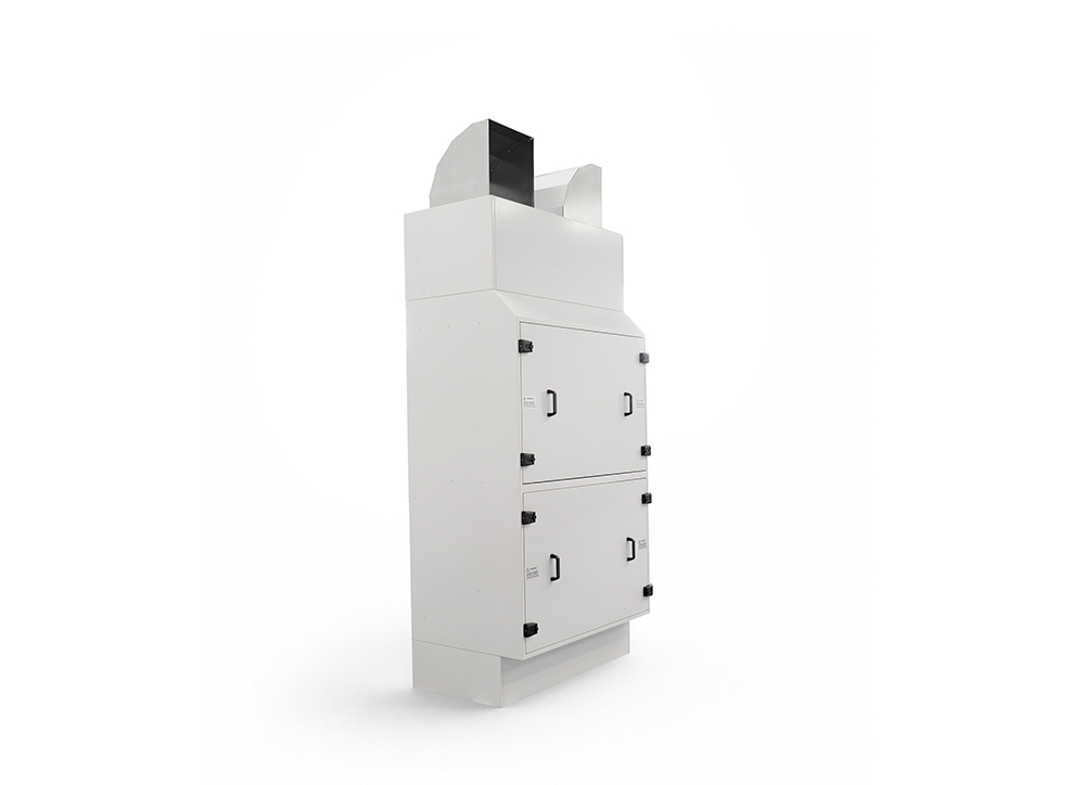
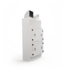
RAHU is a recirculation and treatment unit for the air serving technical rooms, performing the following functions: drawing, filtering, cooling, and returning recirculated air to the rooms it serves.
- Air flows through the unit from bottom to top, in the following sequence:
- Air inlet through the lower silencer;
- Pre-filtration through two G4/Coarse 60% cell pre-filters;
- Return air temperature measurement via a dedicated sensor;
- Cooling through a water/air heat exchange, supplied by a hydraulic circuit external to the machine;
- Air movement via an EC centrifugal fan, variable speed 25-100%;
- Supply air temperature measurement via a dedicated sensor;
- Absolute filtration though two absolute filters;
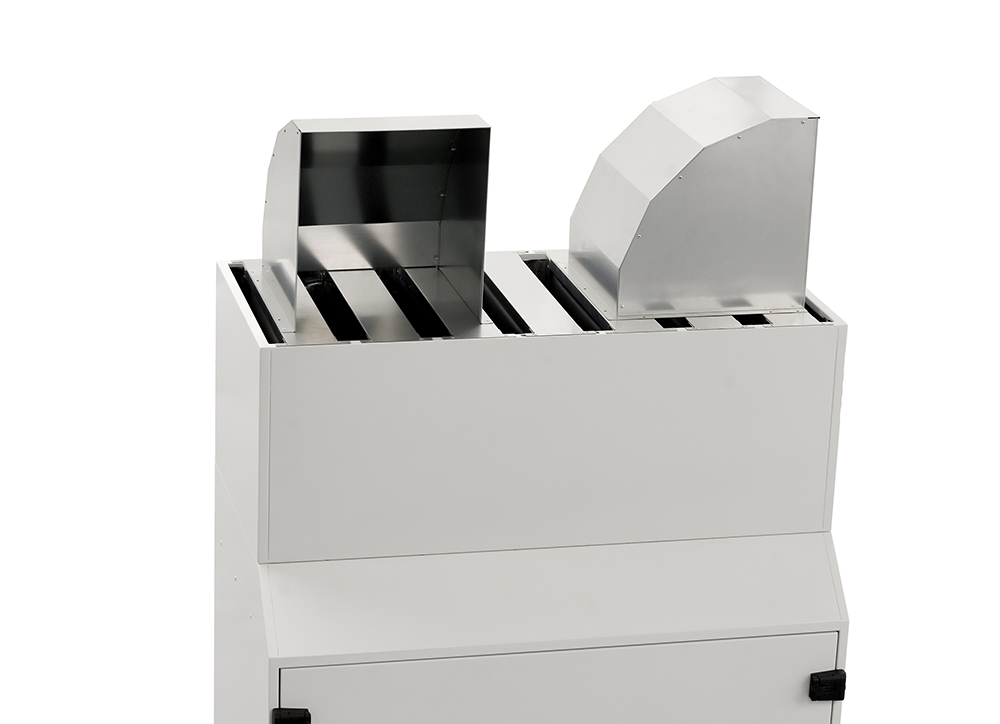
- Air outlet through the upper silencer.
The unit is fully automatic: it receives a general run-enable signal from the customer’s PLC Master and independently regulates the treated air temperature via an on-board PLC, with no operator intervention required. The external hydraulic circuit feeding the heat exchanger (three way mixing valve, piping, control components) is functionally integrated with the RAHU’s control logic but is supplied and installed by the customer.
The RAHU is classified as a machinery under the Machinery Directive 2006/42/EC and carries CE marking.
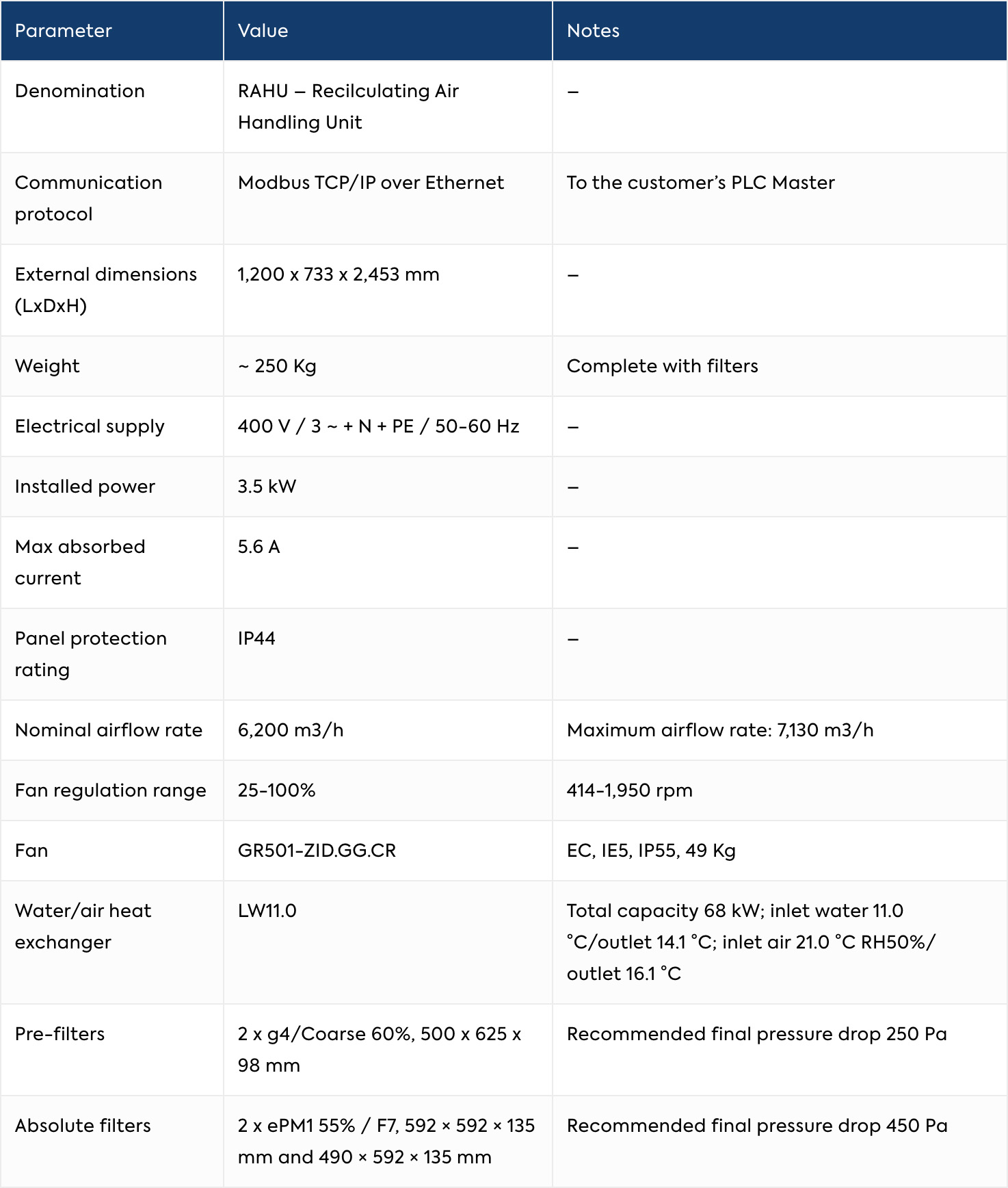
Technical Data
Sound Emission
Measured during functional testing at 9 fan speed settings, from 25& to 100%
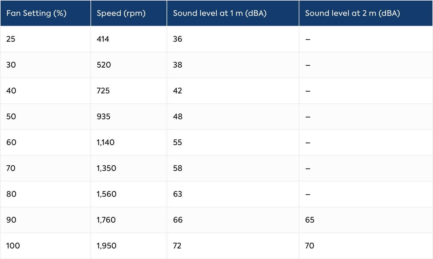
Sound level depends on the operating point set by the customer’s PLC Master. The maximum measured value (72 dBA at 1 m, 100% speed) is below the 80 dB(A) threshold above which the Machinery Directive 2006/42/EC requires the declaration of sound power level LwA.
Applications
Recirculation and air treatment for technical rooms and service areas supporting Cleanrooms in the Pharmaceutical, Biotech, Electronics, Semiconductor, Medical and Laboratory Industries.
Components’ Description
Supporting structure
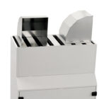
Carbon steel sheet metal frame, 1.2 mm thickness, cut and press-bent, welded and riveted assembly. Rigid, self-supporting boxed body with reinforcements, omega profiles, brackets and functional supports. Conductive white RAL 9010 painted finish. Internal insulation with cross-linked closed-cell adhesive polyethylene panels, faced with smooth aluminum foil, for thermal and acoustic performance. Upper and lower silencers with sound-absorbing glass fibre baffles. EPDM gaskets at module coupling points. Removable front inspection doors on 4 hinges with lever and pressure-relief safety, for front-access maintenance.
Pre-filters (2 units)
Cell pre-filter, G4 (EN 779) / Coarse 60% (ISO 16890) class. Double containment mesh, galvanized steel frame, synthetic fibre media. Maximum operating temperature 70 °C, gravimetric efficiency 90%. Dimensions 500 × 625 × 98 mm; clogging status monitored by a dedicated differential pressure switch.
Return air temperature sensor
Duct-mounted sensor, 0–10 V output, PT1000 class B element, accuracy ± 0.2 °C + 3% FS, IP65.
Water/air heat exchanger
Mounted at a 45° incline. Galvanized steel frame, copper tubes, aluminium fins. Reversible 3/4″ female gas connections (installable on either side of the unit), air vent valve, drain valve. Supplied by a hydraulic circuit external to the machine.
Fan compartment door interlock
Lever-type position switch with roller, wired to a PLC digital input. Protects access to the upper compartment (fan, supply air sensor, absolute filters).
EC centrifugal fan
IE5 efficiency class, IP55, integrated active electronic thermal protection, ball bearings with permanent lubrication. Modbus RS485 communication to the on-board control panel for configuration and diagnostics.
Heat exchanger compartment door interlock
Lever-type position switch with roller, wired to a PLC digital input. Protects access to the lower compartment (pre-filters, return air sensor, heat exchanger).
Supply air temperature sensor
Duct-mounted sensor, same specification as the return air sensor.
Absolute filters (2 units)
Galvanized steel frame, glass fibre media, hot-melt separators. Classification: EN 16890 ePM1 55% / EN 779:2012 F7. Fire classification DIN 53438 Class F1, maximum operating temperature 70 °C. Recommended final pressure drop 450 Pa; clogging status monitored by a dedicated differential pressure switch.
Power panel
Door-interlocked main disconnect switch, protection fuses, 24 Vdc power supply, contactors. Fan acceleration ramp 50 s, deceleration ramp 30 s.
Auxiliary/control panel
On-board PLC with dual Ethernet ports, digital and analogue I/O modules, relays, terminal blocks. Communicates with the customer’s PLC Master over Modbus TCP/IP via Ethernet.
Control System
The RAHU is supervised entirely remotely: there is no local operator interface, and all commands, setpoints and status monitoring are handled through the customer’s BMS/PLC Master via Modbus TCP/IP over a dedicated Ethernet connection.
- Regulation logic — The on-board PLC modulates the opening of the external cooling water valve using a PID algorithm acting on the return air temperature, to bring the recirculated air to the setpoint configured remotely.
- Supply air safety clamp — The system continuously monitors the supply air temperature; if it drops below the configured minimum, the control logic partially closes the cooling water valve, overriding the return-air request, until the supply temperature returns within limits.
- Door interlocks — Opening either inspection door immediately disables the fan; after closing the door, a remote reset command from the PLC Master is required to resume operation.
- Communication loss behaviour — If the Ethernet connection to the PLC Master is lost, the unit holds the last received command values (fail-safe behaviour) until communication is restored.
- I/O interface — Includes digital inputs (fan run feedback, door interlock status, pre-filter and absolute filter clogging pressure switches, power presence), digital output (fan run command), analogue inputs (return/supply air temperature, 0–10V), analogue outputs (fan speed reference, post-cooling valve command), and a Modbus RS485 fieldbus link to the fan for configuration and diagnostics.
Configuration Options
Hydraulic connection (3/4” Gas) installable on either the right or left side of the unit, according to on-site piping layout.
Custom hydraulic and I/O interface points to match the customer’s BMS/PLC Master architecture.


